

Solar Structural Consultancy Services
for Solar Projects in India
Solyug Energy provides structural consultancy and engineering support for solar projects, including rooftop, commercial and industrial (C&I), ground-mounted and other project-specific solar installations. Our structural approach focuses on site conditions, loading requirements, structural stability, constructability and applicable design standards.
A solar PV system is only as reliable as the structure supporting its modules and equipment. Proper structural engineering helps evaluate whether a roof, mounting system, foundation or support frame can safely withstand the loads expected during the project's operating life. The final design should always be based on the actual project location, structure, equipment, soil/site information and applicable engineering requirements.
Rooftop Load-Bearing Evaluation
RCC flat roof, trapezoidal sheet metal, standing seam, and ballast load verification.
Foundation Design & Anchoring
Concrete ballast, chemical anchor bolts, driven pile, and ground screw foundation design.
Material Optimization & Analysis
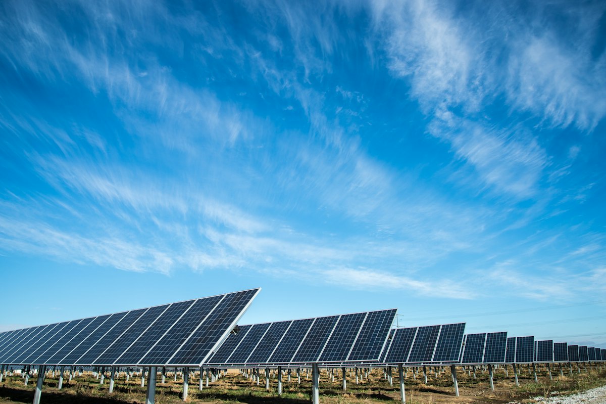
Aluminum vs. HDG steel structural optimization for cost and corrosion longevity.
Our Solar Structural Consultancy Services
We provide project-specific structural engineering support for solar installations. Depending on the scope, services may include:




Structural Design Considerations
for Solar Projects
Every solar structure should be designed around actual project conditions. Important considerations include:
Wind Loads
Wind pressure, uplift, lateral actions and load combinations can govern lightweight solar structures. Site-specific wind parameters and exposure conditions should be evaluated using the applicable standard.
Dead and Live Loads
Dead loads include the permanent weight of modules, rails, mounting members and associated components. Applicable maintenance or imposed loads should also be considered according to the project and governing design requirements.
Seismic Considerations
Where applicable, seismic actions and combinations should be evaluated based on the project's location and the relevant structural design requirements.
Roof and Existing-Structure Capacity
For rooftop installations, the existing building must be considered rather than assuming that every roof can accept a solar array. Available structural drawings, site observations, member sizes, support conditions and relevant loading information should be reviewed as appropriate to the assessment scope.
Soil and Foundation Conditions
For ground-mounted projects, foundation performance depends on the actual site and geotechnical conditions. Soil bearing capacity, pile behaviour, groundwater and other geotechnical parameters can affect foundation selection and design.
Material, Corrosion and Connection Considerations
Solar structures operate outdoors for long periods. Material grade, galvanizing/coating, fasteners, connections, drainage and the project's environmental exposure should be considered when specifying the structural system.
Rooftop vs Ground-Mounted
Solar Structural Design
Rooftop and ground-mounted solar structures have different engineering requirements.
Rooftop Systems
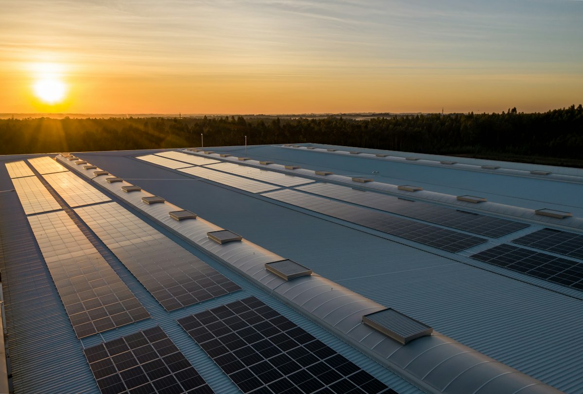
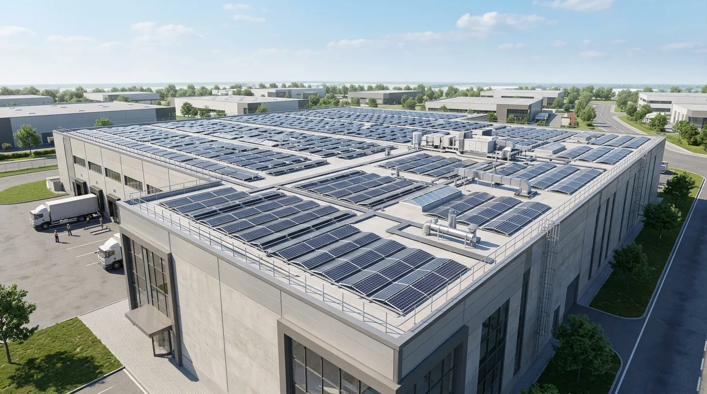
Rooftop systems transfer loads into an existing building and therefore require attention to roof construction, existing members, attachment details, waterproofing interfaces and additional loading.
KEY ENGINEERING CONSIDERATIONS:
- Dead and live load validation under IS 875 (Parts 1 & 2) to ensure existing RCC slabs or PEB purlins safely withstand added module weight.
- Non-penetrative clamp ballasted systems or chemical anchor stud fixtures engineered to maintain roof waterproofing membrane integrity.
- Aerodynamic wind pressure distribution (Cpe/Cpi) accounting for parapet shielding, edge corner vortices, and building height coefficients.
Ground-Mounted Systems
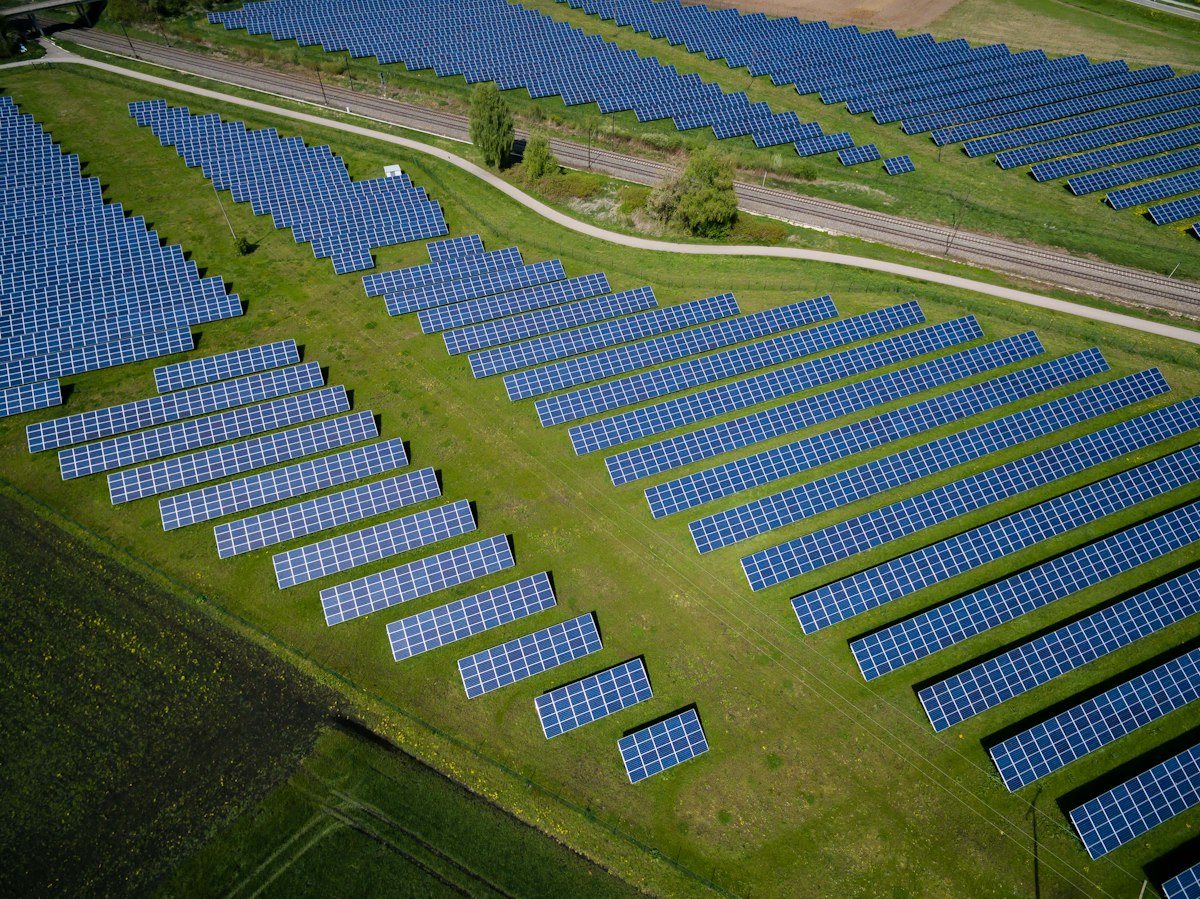
Ground-mounted systems transfer structural loads directly into foundations and underlying soil strata. Engineering requires rigorous geotechnical assessment, foundation selection, terrain grading, and wind-induced overturning analysis.
KEY ENGINEERING CONSIDERATIONS:
- Geotechnical soil bearing capacity (SBC) and pull-out resistance testing for driven pile, concrete stub, or ground screw foundations.
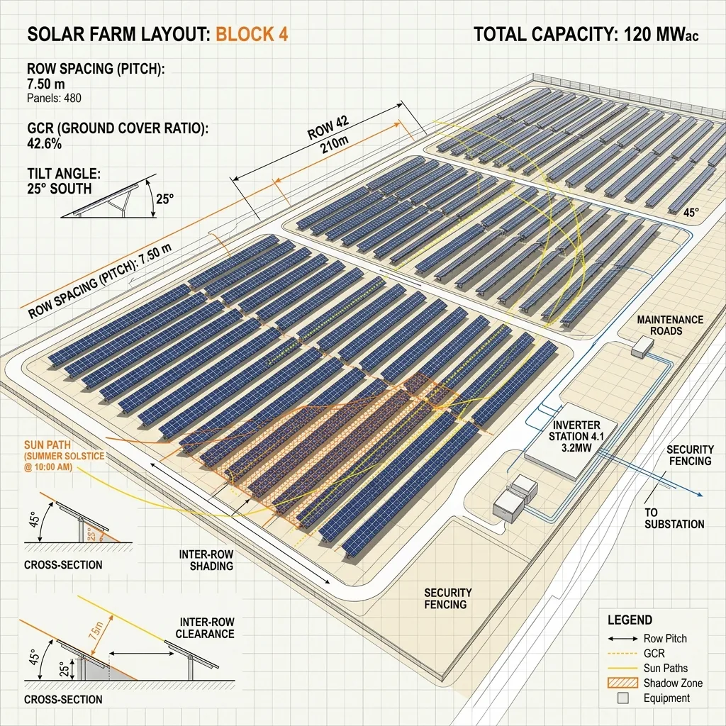
- Pitch and inter-row spacing calculations to eliminate winter inter-row shading while maximizing ground coverage ratio (GCR).
- Terrain contour grading and dynamic wind gust aero-elastic structural modeling under IS 875 Part 3:2015 (up to 55 m/s).
Solar Structural Consultancy Process
Step-by-step breakdown of how our structural engineering team delivers certified designs, loading evaluations, and execution drawings.
Project brief and scope definition.
Establishing clear project boundaries, structural requirements, target codes (IS 875, IS 800), and client deliverables before engineering begins.
Collection of drawings, site information and equipment data.
Gathering architectural drawings, soil investigation reports, roof layouts, PV module datasheets, and structural loading requirements.
Review of project location and applicable design requirements.
Matching site GPS coordinates with wind zone maps, seismic zones (IS 1893), terrain category, and micro-climate environmental exposures.
Review of solar layout and mounting arrangement.
Evaluating PV table orientation, tilt angle, purlin spacing, rafter spans, and clearance heights for optimized structural response.
Definition of design loads and load combinations.
Calculating dead loads, live loads, wind speed adjustments (Vz, Pz), suction uplift (Cpe - Cpi), and seismic forces under governing standards.
Structural modelling and analysis where required.
3D finite element structural modeling in STAAD.Pro to evaluate axial forces, bending moments, shear stresses, and deflection limits.
Member, connection and support/foundation checks.
Verification of purlin/rafter stress ratios, bolt shear/bearing capacities, anchor pullout strength, and concrete ballast/stub foundation sizing.
Design optimization and coordination with other engineering disciplines.
Refining steel/aluminum section profiles to optimize material weight while coordinating structural clearance with electrical cable trays and walkways.
Preparation of drawings/reports included in the agreed scope.
Drafting detailed GA drawings, fabrication blueprints, foundation layouts, and compiling certified structural calculation reports.
Technical review and final submission.
Internal quality review by chartered structural engineers, final verification, and client delivery for site execution and regulatory submission.
Solar Mounting &
Structural Engineering Consultancy
From industrial rooftop load-transfer verifications to MW-scale ground-mount foundation engineering, Solyug Energy provides certified structural design packages compliant with IS 875, IS 800, and international bankability criteria.
What Is Solar Structural Consultancy?
Solar structural consultancy is the engineering assessment, analysis, design review and documentation required to make the supporting structure of a solar installation safe, stable and suitable for the project. Depending on the scope, our work covers existing-roof assessment, module mounting structures (MMS), rooftop support systems, ground-mounted structures, foundations, load calculations, wind-load analysis, structural modelling, design validation and engineering reports/drawings.
Why Structural Engineering Is Critical for Solar Projects
Solar modules, mounting structures, cables and associated equipment introduce permanent and environmental loads into a project. Wind can create significant uplift and lateral forces on tilted PV arrays, while seismic effects, existing-building conditions, soil characteristics, connections, corrosion and construction quality can affect long-term structural performance. A project-specific structural assessment helps identify design constraints before installation, eliminating the risk of over-design, under-design, or catastrophic structural failure.
Our structural engineering packages integrate directly with our Detailed Engineering Design (DED) and 3D Shadow Analysis workflows to optimize structure stability, tilt angle, and bill of materials (BOM).
Typical Deliverables
Depending on the project scope, deliverables may include:
01. Design basis and structural assumptions
IS 875 CRITERIAComprehensive structural design criteria documentation defining applicable IS/ASCE codes, dead loads, live loads, and regional wind zoning parameters.
02. Load Calculations
LOAD COMBINATIONSExhaustive dead, live, wind uplift, dynamic gust, and seismic load combination matrices computed per IS 875 (Parts 1-3) & IS 1893.
03. Structural Analysis Report
PE STAMPED REPORTComplete member stress, unity ratio (<1.0), nodal deflection, and critical member capacity reports with 3D force distribution plots.
04. STAAD Pro model/analysis outputs where included
STAAD.PRO FEANative .STD STAAD.Pro finite element numerical models, beam-node tables, bending moment envelopes, and shear force validation diagrams.
05. Rooftop structural assessment
SLAB & PEB AUDITPoint load transfer checks on existing RCC slabs, PEB purlins, rafters, and deck sheets to guarantee zero structural overloading.

11. Design validation comments
CE COMPLIANCEThird-party peer review, CEIG submission vetting, and certified Chartered Engineer (CE) structural safety endorsement certificates.
06. Solar mounting structure calculations
CFS / POSMAC SIZINGCold-formed steel (CFS) and hot-rolled section sizing, purlin/rafter optimization, and corrosion-resistant PosMAC/galvanized coating specs.
07. General arrangement or structural drawings
2D/3D AUTOCAD GADetailed 2D/3D AutoCAD fabrication drawings, foundation layout plans, column-to-baseplate detailing, and hardware connection schedules.
08. Foundation design information
SOIL INTERACTIONGeotechnical soil-structure interaction analysis for RCC stub pedestal, direct driven pile, micro-pile, and chemical anchor bolt designs.
09. Structural recommendations and limitations
EXECUTION LIMITSExplicit torque specifications, foundation curing tolerances, corrosion protection guidelines, and permissible structural modification boundaries.
10. Material/member specifications
BOM & SPECSMaterial test certificates (MTC) grade compliance, yield strength (YSt 350/550 MPa), zinc coating GSM specs, and SS304/SS316 fastener schedules.
Project Inputs Required for Structural Certification
What Information Do We Need From the Client?
Typical inputs may include project location, solar plant capacity, module dimensions and weight, inverter/equipment information where relevant, rooftop drawings or structural drawings, existing building information, solar layout, mounting-structure details, soil/geotechnical information for ground-mounted projects, site photographs and the intended design standard or client specification. Providing accurate project information early helps reduce assumptions and redesign during the engineering process.
Why Choose Solyug Energy?
Solyug Energy is a solar design and consultation company providing engineering support for solar projects. The company states that it has completed 520+ MW of solar projects across India, Africa and Gulf countries. Its broader service portfolio includes detailed engineering design, ground-mount MW-scale project design, PVsyst power-generation reports, STAAD Pro wind analysis, CEIG electrical approval drawings, SketchUp 3D design, DPR preparation and project ROI calculation. This integrated solar engineering capability allows structural work to be coordinated with the overall PV design instead of being treated as an isolated structural package.
Request a Solar Structural
Engineering Consultation
Planning a rooftop, C&I or ground-mounted solar project and need structural engineering support?
Share your project location, solar capacity, available structural drawings/site information and mounting-structure requirements with Solyug Energy. We can review the available inputs and recommend the appropriate structural assessment, analysis and documentation scope.